Connect SDI-12 sensors fast, read values over BLE, and reuse the same workflow for additional sensors.
Overview diagram:
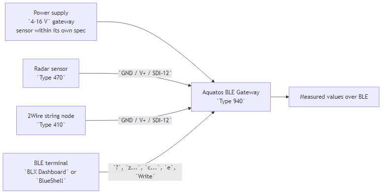
This handbook shows how to connect:
Aquatos BLE Gateway, Type 940OSX Radar Distance 60 GHz, Type 470OSX 2Wire String Node, Type 410It also gives a reusable setup pattern for
other SDI-12 sensors.
Important
Aquatos BLE is the SDI-12 master. You
connect the sensor to the gateway, then operate the whole setup over
BLE with BLX Dashboard (preferred) (or
BlueShell).
Important
The gateway itself has no SDI-12 address. It addresses
the connected sensors by their own SDI-12 addresses such as
0, 1, 2, ... or by broadcast
?.
Important
Broadcast ? is safe only if there is
exactly one sensor on the SDI-12 bus. With multiple
sensors, it can cause collisions,
garbled replies, or bad CRC.
Simple setup procedure:
one by one0z?!
to discover its current address quicklyz0I! if you expect the
default address 0z0?X!,
where X is the new address > 01 for the radar sensor
and address 2 for the 2Wire nodeM commandsc... command on the gateway to poll
all sensors with their real addresses, for example
c1MC:0-1 2MC for a radar at address 1 and a
2Wire node at address 2.Note
? is useful if the sensor address is unknown, but only
when exactly one sensor is connected to the bus. If you are
unsure about SDI-12 addressing, address changes, or broadcast behavior,
check https://SDI-12.org.
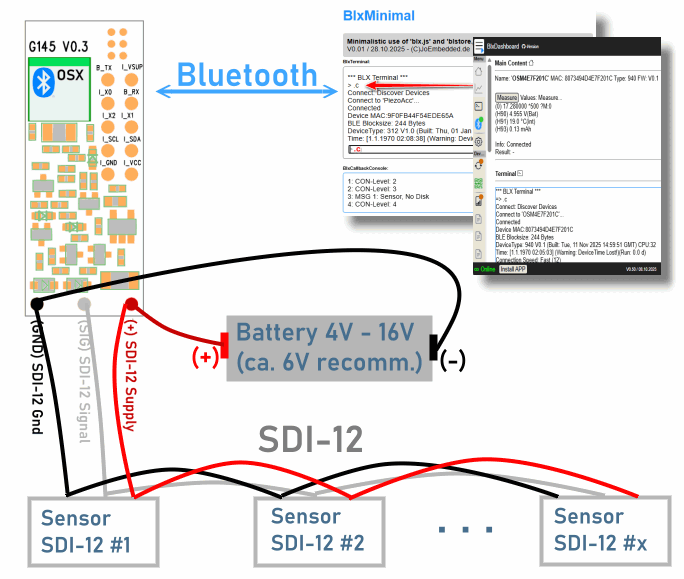
For the gateway and both OSX sensors, the SDI-12 cable mapping is effectively:
| Function | Aquatos BLE | Sensor side |
|---|---|---|
GND |
black |
black |
V+ |
red/brown |
brown |
SDI-12 data |
white |
white or blue |
4-16 V, recommended
6 V (e.g. 4 * 1.5V AA batteries)Caution
Check polarity before power-up. The documentation explicitly warns
that most sensors are not reverse-polarity protected.
Tip
Start with a single shared supply around 6 V. That fits
the gateway and both sensor types and keeps field setup simple.
Connect to the gateway with BLX Dashboard or
BlueShell, then use this baseline sequence (examples):
?
z0I!
z0?1!
z2I!
c1MC:0-1 2MC
e
Write
What each command does (commands on the gateway):
? shows the current gateway status and stored
CMDz0I! reads the ID string of sensor address
0z1I! reads the ID string of sensor address
1z?! sends the SDI-12 broadcast address query and is
useful if the address is unknown, but only works safely if
exactly one sensor is on the busz0?1! changes a newly connected sensor from address
0 to address 1c... sets the gateway measurement command line, but
does not store it permanently. Test first, then save it with
Write. *1000 would set a timeout of
1000 ms; the default is already 500 ms, so use
a longer timeout only if a sensor needs more time to wake up.e runs a measurement and prints values over BLEWrite saves the configuration permanently (on the
gateway's flash memory)Caution
Do not use broadcast ? on a
multi-sensor bus. With more than one sensor, broadcast can cause
collisions, garbled data, or
bad CRC because multiple sensors may answer at the same
time.
Tip
Top Tip for Debugging the c command on the
gateway Enable raw SDI-12 logging in the gateway terminal
before testing e so you can see exactly which SDI-12
commands the stored c... sequence triggers.
z dbg 1
e
z dbg 0GND, V+, and
SDI-12 data?z?!. If multiple sensors are on the bus, use only
known addresses such as z0I!, z1I!, and so
on.c...eWriteNote
The gateway command stored with c... must be entered
without the final SDI-12 !.
Tip
Simple commissioning workflow for multiple sensors: newly connected
sensors are usually at address 0, so connect them
one by one, verify them with z0I! or, if the
address is unknown, with z?! while only one sensor is on
the bus, then change them immediately to their own address with
z0?X!. In this guide, the radar uses address 1
and the 2Wire node uses address 2.
Important
You can communicate either with the gateway or also with the SDI-12 nodes directly via BLE. Here only communication via Gateway is covered. For direct communication with the sensors see their appropriate documentation.
Type 470Use this profile if you want distance and
signal strength from the radar node.
Typical direct check:
z0I!Or if there is only one sensor connected to the bus and
its address is unknown, you can use ? as broadcast
address:
z?!You should receive an ID string containing Radar and
0470. In any case, the sensor will reply with its real
address.
It depends how many data to read from the sensor. Here 2 values are read: (main) distance and signal strength. The command is:
Without CRC:
c1M:0-1With CRC:
c1MC:0-1These commands give exactly 2 values. To read all values
from the radar at address 1, omit the : block
in the c command. For the radar, that gives 6
values: 3 distances and 3 signal-strength
values.
c1MNewly connected sensors are usually at address 0. Change
the radar to address 1 immediately after identification
with the Address Change command:
z0A1!Why this works:
1M or 1MC starts the radar measurement on
address 1:0-1 keeps only the first two returned valuesImportant
This example assumes the radar sensor is at address 1.
On a bus with multiple sensors, use the real sensor address, for example
1M:0-1 for address 1. Do not rely on broadcast
once more than one sensor is connected.
e runs the measurement and prints values over BLE. If
the output looks correct, note it:
eNote
The setup command c... is not stored permanently until
you run Write. This allows you to test different commands
first and only save the one that works best for your setup.
Tip
For first setup, start with c1M or c1M:0-1.
Add CRC later for stricter bus validation (not necessary for quick
tests).
Type 410Next a 2Wire node is added (physically connected) to the same bus (e.g. a thermistor string).
The 2Wire node can return up to 8 values for M.
Note
A newly connected node will often (if not already
changed) be at address 0. If you plan to use multiple
sensors on one bus, give each sensor its own address before combining
them on the same cable. In this guide, the radar sensor's address was
moved to address 1, so the new 2Wire node can still be
found at address 0 and then changed to address
2.
Test:
z0I!You should see an ID string containing TN_2W_0410 or
Type 410.
Change its address if needed, for example to 2:
z0?2!M or MC returns the first measurement
blockM1, M2, ... return additional blocks
if more than 9 values exist)M9 can return the node supply voltageFor 1-8 temperature nodes (short temperature list), start with e.g.
for SDI-12 address 2:
c2MCAdditional info: If the chain is longer than one output block, extend it explicitly, for example:
```
c2MC 2MC1 2MC2
```
This lets the gateway poll when the sensor address is `2`:
- first block with `2MC`
- second block with `2MC1`
- third block with `2MC2`eImportant
A Type 410 installation may contain many sensors. If you
expect more than 9 returned values, add further blocks such
as 2MC1, 2MC2, and so on.
c
commandAssemble the final c... command for the gateway to poll
both the radar and the 2Wire node, for this example:
c1MC:0-1 2MCe
WriteImportant
Only after running Write is the current
c... command stored permanently on the gateway. You can
change it later if needed, but make sure to test new commands first
before saving them.
Quick checks:
z?! returns nothing, verify GND,
V+, and data, or remember that broadcast only
works safely with a single sensor on the busz0I! fails, the sensor address is probably not
0one by one to assign
unique addresses firstc*1500 ...z dbg 1Note
If you are unsure about SDI-12 addressing rules, address changes, or
broadcast behavior, remember that ? is only for a
single-sensor bus and check https://SDI-12.org.
black, brown, white/blue
wired correctly0 and should be moved quickly to addresses such as
1, 2, ...z?! used only on a single-sensor busz0I!, z1I!, or
similarc... command storedeWrite? -> show gateway status
z?! -> broadcast address query if the address is unknown,
only for a single-sensor bus
z0I! -> read sensor ID at address 0
z1I! -> read sensor ID at address 1
z0?1! -> move a newly connected radar sensor from address 0 to address 1
z0?2! -> move a newly connected 2Wire node from address 0 to address 2
z0?X! -> change sensor from address 0 to a ddress X > 0
c1MC:0-1 -> radar quick setup if the sensor is at address 1
c2MC -> 2Wire first block with CRC, address 2
c2MC 2MC1 2MC2 -> 2Wire multi-block example if the sensor is at address 2
e -> run measurement and print values
Write -> save permanently
z dbg 1 -> enable SDI-12 debug output
z dbg 0 -> disable SDI-12 debug output