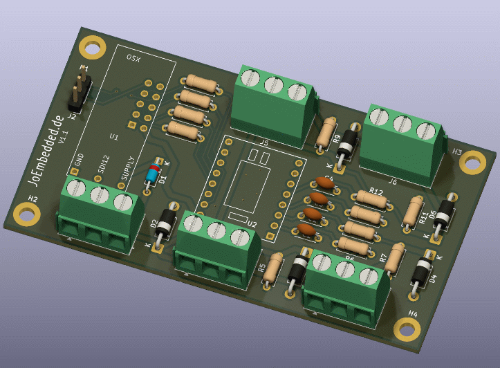
PCB V1.1 for 0/4-20 mA (other versions: PT100, bridge, ...)
The T350 ("OSX Typ350") is a highly precise, universal analog data
acquisition node based on the ADS1220. It supports up to 8
physical measurement channels (operating modes), which are
fixedly configured via the array ad_physkan[] in the
firmware source.
Typical applications:
| Signal | Pin | Color (Cable) | Direction at ADC |
|---|---|---|---|
| SCLK | IX_SCL | yellow | IN |
| DIN (MOSI) | IX_SDA | green | IN |
| DO / #DRDY | IX_X0 | white | OUT |
| #DRDY | IX_X1 | blue | OUT |
| #Vcc (Pwr) | IX_X2 | – | LOW = ON |
Note
The ADS1220 operates with #CS permanently pulled LOW (SPI Mode 1, CPOL=0, CPHA=1). After power off, IX_X2 pulls the SPI lines to GND via 2 × 15 kΩ resistors.
ad_physkan[])The firmware knows 8 physical channels (indices
0–7). Each channel has a fixed configured operating mode
(typ), ADS1220 register configuration, averaging, and
unit.
typ)typ |
Constant | Description |
|---|---|---|
| 1 | P_TYP_ITEMP |
Internal chip temperature of the ADS1220 |
| 2 | P_TYP_PT100_A |
PT100 via 2 kΩ reference + IDAC 1 mA + polynomial linearization |
| 3 | P_TYP_STD |
Standard ADC (single-ended or differential), result in mV or counts |
| Idx | SDI-12 Cmd | Type | Configuration | SPS | Averaging | Calibration | Unit | Measurement Time |
|---|---|---|---|---|---|---|---|---|
| 0 | M2 | 1 | Internal temperature | 45 | 1× | no | oC_int |
~22 ms |
| 1 | M3 | 2 | PT100 (ext. reference, IDAC) | 45 | 8× | yes | oC_PT100 |
~453 ms |
| 2 | M4 | 3 | Single-Ended AIN0 | 45 | 4× | yes | mV_S0 |
~275 ms |
| 3 | M5 | 3 | Single-Ended AIN1 | 45 | 4× | yes | mV_S1 |
~275 ms |
| 4 | M6 | 3 | Single-Ended AIN2 | 45 | 4× | yes | mV_S2 |
~275 ms |
| 5 | M7 | 3 | Single-Ended AIN3 | 45 | 4× | yes | mV_S2 |
~275 ms |
| 6 | M8 | 3 | Differential AIN0–AIN1 | 45 | 8× | yes | mV_D01 |
~453 ms |
| 7 | M9 | 3 | Differential AIN2–AIN3 | 45 | 8× | yes | mV_D23 |
~453 ms |
Calibration (Cali-Flag): When active, an offset zero point is automatically determined and subtracted before the actual measurement by internally shorting the inputs (AIN_p/n to AVDD/2). This approximately doubles the measurement time.
oC_int)ITEMP_CONFIG = 0x5022E0
TS_ENA (internal temperature sensor active),
single-shot, external reference (irrelevant), FIR 50/60 HzoC_PT100)Note
Hardware must support PT100
T = c0 + c1 ⋅ x + c2 ⋅ x2
with the linearization:
c0 = −2.457390 × 10², c1 = 7.022650 × 10⁻⁵, c2 = 8.966090 × 10⁻¹³
PT100_CONFIG = 0x80562406
Caution
If the raw value is outside the valid range, the PT100 channel returns –99 °C (sensor break or range exceeded –70 … +120 °C).
mV_…)SE_MULTI_G1 = 2.4414e-4 (2.4414 ×
10⁻⁴) → result in mVSE_CONFIG = 0x102481DE_MULTI_G128 = 1.907e-6 (1.907 ×
10⁻⁶) → result in mVDE_CONFIG = 0x10240ENote
Hardware for 0/4–20 mA current measurement must include a 100 Ohm shunt resistor. For bridge measurement, the bridge should be set to a level of approx. 1 V, e.g., via a high-impedance voltage divider.
Note
Measurement is performed with the standard SDI-12 commands
aM!, aM1! … aM9! (and of course
also combined with CRC: aMC!, aMC1! …
aMC9!). Here only the commands M and later
X and I are documented; all other commands
correspond to SDI-12 standard V1.3 (see SDI-12 specification).
| Command | Channels | Description |
|---|---|---|
aM! |
All active channels | Measures all channels whose bit in the m0_mask register
is set |
aM1! |
All active + VSup | Like M, additionally supply voltage (VSup)
as the last channel |
aM2! |
Channel 0 (internal temp) | Only internal chip temperature (oC_int) |
aM3! |
Channel 1 (PT100) | Only PT100 temperature (oC_PT100) |
aM4! |
Channel 2 (SE AIN0) | Only single-ended channel AIN0 (mV_S0) |
aM5! |
Channel 3 (SE AIN1) | Only single-ended channel AIN1 (mV_S1) |
aM6! |
Channel 4 (SE AIN2) | Only single-ended channel AIN2 (mV_S2) |
aM7! |
Channel 5 (SE AIN3) | Only single-ended channel AIN3 (mV_S2) |
aM8! |
Channel 6 (DE AIN0–AIN1) | Only differential AIN0–AIN1 (mV_D01) |
aM9! |
Channel 7 (DE AIN2–AIN3) | Only differential AIN2–AIN3 (mV_D23) |
a= SDI-12 address of the sensor (default:0)
Error values in measurement result:
| Value | Meaning |
|---|---|
–99 |
PT100: Outside measuring range / break |
–9998 |
ADC initialization error |
–9999 |
General measurement error |
X commands)All configuration commands start with aX followed by the
command letter. For reading, no = sign is
used, for writing use =Value. Each command
ends with !.
Warning
All parameter changes are volatile (RAM). Only
aXWrite! saves them permanently in Flash (NVM).
K) – Individual scaling per channelEach physical channel has 2 coefficients:
Multi (even index) and Offset (odd index).
Application order:
Result = (ADC raw value × channel multi) × Kn_Multi − Kn_OffsetCoefficient table:
| No. | Name | Default |
|---|---|---|
| K0 | Temp_int.Multi | 1.0 |
| K1 | Temp_int.Offset | 0.0 |
| K2 | Temp_PT100.Multi | 1.0 |
| K3 | Temp_PT100.Offset | 0.0 |
| K4 | SEnd_0.Multi | 1.0 |
| K5 | SEnd_0.Offset | 0.0 |
| K6 | SEnd_1.Multi | 1.0 |
| K7 | SEnd_1.Offset | 0.0 |
| K8 | SEnd_2.Multi | 1.0 |
| K9 | SEnd_2.Offset | 0.0 |
| K10 | SEnd_3.Multi | 1.0 |
| K11 | SEnd_3.Offset | 0.0 |
| K12 | Diff_01.Multi | 1.0 |
| K13 | Diff_01.Offset | 0.0 |
| K14 | Diff_23.Multi | 1.0 |
| K15 | Diff_23.Offset | 0.0 |
Syntax:
| Command | Function | Example |
|---|---|---|
aXKn! |
Read coefficient n | 0XK2! |
aXKn=Value! |
Set coefficient n | 0XK3=0.5! |
Response: aKn=Value (e.g.,
0K3=0.500000)
B) – Active channels for M / M1The bitmask m0_mask (1 byte) controls which channels are
measured with M and M1.
Bit 0 → Channel 0 (iTemp), Bit 1 → Channel 1 (PT100), ..., Bit 7 →
Channel 7 (DE23).
Default value: m0_mask = 60 =
0b00111100 → Channels 2, 3, 4, 5 active (SE AIN0–AIN3)
60 = 4 + 8 + 16 + 32 = Bit 2 + Bit 3 + Bit 4 + Bit 5
| Command | Function | Example |
|---|---|---|
aXB! |
Read current mask | 0XB! |
aXB=Value! |
Set mask (1–255 decimal) | 0XB=60! (only SE AIN0–AIN3) |
Response: aB=Value (e.g.,
0B=60)
Bit assignment of channels:
| Bit | Bit Value | Channel | Description | Active with m0_mask=60? |
|---|---|---|---|---|
| 0 | 1 | 0 | Internal Temperature | no |
| 1 | 2 | 1 | PT100 | no |
| 2 | 4 | 2 | SE AIN0 (mV_S0) | yes |
| 3 | 8 | 3 | SE AIN1 (mV_S1) | yes |
| 4 | 16 | 4 | SE AIN2 (mV_S2) | yes |
| 5 | 32 | 5 | SE AIN3 (mV_S2) | yes |
| 6 | 64 | 6 | Diff AIN0–AIN1 | no |
| 7 | 128 | 7 | Diff AIN2–AIN3 | no |
Example: Enable all SE channels + PT100
0XB=62!        62 = 2+4+8+16+32 (PT100 + SE AIN0…AIN3)
0XWrite!
Channel active status and full
koutput → Section 5.1.
U) – Override channel labelEach channel has a default unit from ad_physkan[] (e.g.,
oC_PT100). This can be overridden per channel (max. 8
characters). If empty string is used, the default unit is applied.
| Command | Function | Example |
|---|---|---|
aXUn! |
Read unit of channel n | 0XU1! |
aXUn=Text! |
Set unit of channel n | 0XU1=degC! |
aXUn=! |
Reset unit of channel n | 0XU1=! |
Response: aUn='Text' (e.g.,
0U1='degC')
P) – Decimal placesSets the number of decimal places for the SDI-12 output (0–9).
Special values 7, 8, 9: standard format %+f (printf
default).
Format codes:
| P-value | Format | Example output |
|---|---|---|
| 0 | %+.0f |
+23 |
| 1 | %+.1f |
+23.4 |
| 2 | %+.2f |
+23.45 |
| 3 | %+.3f |
+23.450 |
| 4–6 | … | … |
| 7–9 | %+f |
printf-default |
| Command | Function | Example |
|---|---|---|
aXPn! |
Read precision of channel n | 0XP1! |
aXPn=Value! |
Set precision of channel n (0–9) | 0XP1=3! |
Response: aPn=Value (e.g.,
0P1=3)
| Command | Function |
|---|---|
aXWrite! |
Save all parameters (SDI address, coefficients, mask, units, precision) permanently in flash |
aXSensor! |
Query sensor type → response: aADS1220! |
Important
aXWrite! must be explicitly called after
each configuration change – otherwise all changes are
lost on the next restart.
These commands are available via the serial debug interface (tb_tools UART).
device_type_cmdline)| Command | Function |
|---|---|
k |
Output all coefficients (K0–K15) with names, current value, unit, precision, and active status (ON/bit number) |
p |
(Reserved, no function) |
Example output k (with m0_mask = 60
– only SE AIN0…AIN3 active):
>k
K0: 1.000000 Temp_int.Multi(f) (Def: 1.0) Unit:'oC_int' Prec:2 OFF(1)
K1: 0.000000 Temp_int.Offset(f) (Def: 0.0)
K2: 1.000000 Temp_PT100.Multi(f) (Def: 1.0) Unit:'oC_PT100' Prec:3 OFF(2)
K3: 0.000000 Temp_PT100.Offset(f) (Def: 0.0)
K4: 1.000000 SEnd_0.Multi(f) (Def: 1.0) Unit:'mV_S0' Prec:9 ON(4)*
K5: 0.000000 SEnd_0.Offset(f) (Def: 0.0)
K6: 1.000000 SEnd_1.Multi(f) (Def: 1.0) Unit:'mV_S1' Prec:9 ON(8)*
K7: 0.000000 SEnd_1.Offset(f) (Def: 0.0)
K8: 1.000000 SEnd_2.Multi(f) (Def: 1.0) Unit:'mV_S2' Prec:9 ON(16)*
K9: 0.000000 SEnd_2.Offset(f) (Def: 0.0)
K10: 1.000000 SEnd_3.Multi(f) (Def: 1.0) Unit:'mV_S2' Prec:9 ON(32)*
K11: 0.000000 SEnd_3.Offset(f) (Def: 0.0)
K12: 1.000000 Diff_01.Multi(f) (Def: 1.0) Unit:'mV_D01' Prec:9 OFF(64)
K13: 0.000000 Diff_01.Offset(f) (Def: 0.0)
K14: 1.000000 Diff_23.Multi(f) (Def: 1.0) Unit:'mV_D23' Prec:9 OFF(128)
K15: 0.000000 Diff_23.Offset(f) (Def: 0.0)
Bitmask Channels: 60
The column at the end of the line indicates:
ON(BitValue)* – Channel is active (bit in
m0_mask set)OFF(BitValue) – Channel is inactive (bit not set)#define DEBUG is active)Tip
Debug commands are only available if #define DEBUG is
active in the firmware.
| Command | Function |
|---|---|
a<n> |
Measure channel n (0–7) in continuous loop and output raw value, runtime and physical result. Exit with any key. |
Example output a1 (PT100):
Val:1
AD-Reset: 0
Res:3456789 (P:470/Real:463 msec) => +21.456 oC_PT100
Res:3456901 (P:470/Real:461 msec) => +21.458 oC_PT100
...
AD-DeepsleepAll changeable operating parameters are stored in the internal flash of the processor:
| Parameter | Contents |
|---|---|
param.koeff[] |
16 float coefficients (K0–K15) |
param.m0_mask |
Channel mask for M / M1 |
param.precision[] |
Output precision per channel (0–9) |
param.ind_unit[] |
Individual units per channel |
param.ble_advname |
BLE advertising name |
| SDI-12 address | Stored under ID_INTMEM_SDIADR |
Storage is performed exclusively by
aXWrite!(→ Section 4.5).
The sensor ID has the following format:
TT_A24_A_0350_OSX<MAC_Low_HEX>Example: TT_A24_A_0350_OSX1A2B3C4D
TT = TT (internal identifier)A24 = Analog Sensor 24 BitA = Software identifier0350 = Device typeOSX = OSX master platform<MAC> = Lower 32 bits of the BLE MAC address
(corresponds to standard BLE advertising name)| Parameter | Default value |
|---|---|
| SDI-12 address | 0 |
| m0_mask | 60 (channels 2–5 active: SE AIN0…AIN3) |
| Precision | K0:2, K1:3, K2–K7:9 (printf-default) |
| All coefficients | Multi=1.0, Offset=0.0 |
| Individual units | empty (channel default) |
aM!           Measure all active channels
aM1!          Measure all active channels + supply voltage
aM2! – aM9!   Measure single channel 0–7
aXKn!         Read coefficient n
aXKn=val!     Set coefficient n
aXB!          Read channel mask
aXB=val!      Set channel mask (e.g., 60 = only SE AIN0…AIN3)
aXUn!         Read channel n unit
aXUn=str!     Set channel n unit
aXPn!         Read channel n precision
aXPn=val!     Set channel n precision (0–9)
aXWrite!      Save parameters in flash
aXSensor!     Query sensor type